

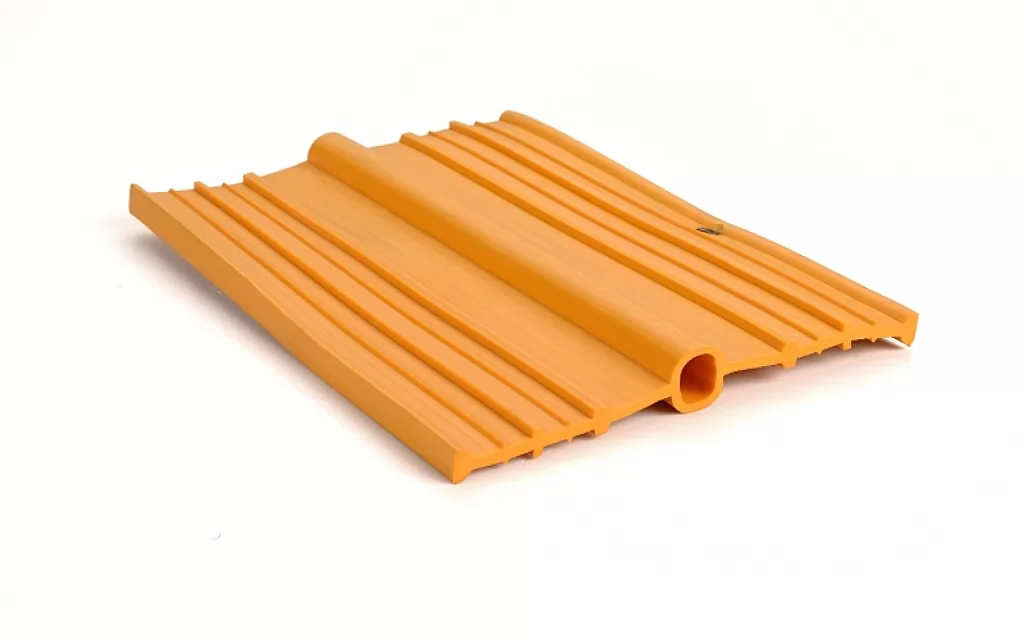


SO Series PVC Waterstop — Internal Expansion Joint
- MaterialPVC (Polyvinyl Chloride)
- Joint typeExpansion / movement joint
- PlacementInternal (center-set)
- ColorBlue
- Size range200 mm – 320 mm width
- ModelsSO200, SO250, SO320
Contact Us Now
The SO Series PVC waterstop is designed for internal expansion joints in concrete structures where a continuous watertight barrier must be maintained across a joint designed to accommodate movement. The strip is installed centrally — half its width embedded in each concrete pour — so the center bulb sits directly over the joint gap and the ribbed wings anchor into the surrounding concrete on both sides.
When the joint opens, closes, or shifts laterally under thermal cycling, settlement, or structural load, the center bulb flexes and stretches to absorb the movement without tearing or losing seal continuity. The ribbed wings remain fully locked in the cured concrete, resisting hydrostatic pressure from either face.
Compared with a flat-profile construction joint waterstop, the SO Series incorporates a center bulb specifically designed to flex with joint movement. This makes it suitable for expansion joints and movement joints where ongoing displacement is expected after the concrete has hardened, rather than for static construction joints where the two pours are intended to cure into a single monolithic element.
Typical applications include reservoirs and water storage tanks, sewage and water treatment plant structures, below-grade basements and underground car parks, dams and spillways, retaining walls, tunnels, and any reinforced concrete structure incorporating designed expansion or movement joints.
The center bulb spans the joint gap; ribbed wings anchor into each pour and resist water migration along the strip surface.
Three standard width configurations cover the most common expansion joint requirements. All models incorporate a center bulb and ribbed wings and are suitable for movement joints where ongoing displacement is expected.
| Model | Nominal Width (mm) | Profile Height (mm) | Typical Application |
|---|---|---|---|
| SO200 | 200 | 20 | Standard expansion joints in moderate-duty concrete structures |
| SO250 | 250 | 24 | General-purpose expansion joints — most commonly specified width |
| SO320 | 320 | 24 | Larger joint layouts, high-head applications, dams and tunnels |
| Dimensions are nominal values. Detailed cross-section drawings and roll lengths are available on request — see the inquiry form below. Custom widths available subject to minimum order quantity. | |||
All SO series waterstops are extruded from PVC compound and tested against ASTM-referenced methods for the properties below.
| Property | Type I | Type II |
|---|---|---|
| Shape | Thermoplastic extrusion ribbon | Thermoplastic extrusion ribbon |
| Color | Blue | Blue |
| Hardness | 70–90 Shore A | 70–90 Shore A |
| Tensile Strength | ≥ 12 MPa | ≥ 14 MPa |
| Elongation at Break | ≥ 250% | ≥ 320% |
| Density | ≥ 1,300 kg/m³ | ≥ 1,300 kg/m³ |
| Water Absorption | ≤ 0.5% | ≤ 0.5% |
| Toxicity | Non-toxic | Non-toxic |
SO Series internal expansion joint waterstops are specified wherever a reinforced concrete structure incorporates designed movement joints that must remain watertight throughout the structure's service life. Common project types include:
Both the SO Series and the BC Series are internal expansion joint waterstops with a center-bulb profile designed to accommodate movement. The BC Series offers a wider range of width configurations — eight sizes from BC150 to BC500x10 — and includes heavier-duty variants with reinforced flanges and increased rib counts for high-displacement or large-section applications. The SO Series covers the three most common mid-range widths (SO200, SO250, SO320) suited to standard reinforced concrete structures. Refer to your structural drawings and consult our team to confirm the appropriate series and width for your project.
The SO Series is used for internal expansion joints in reinforced concrete structures where water-tightness across the joint line is required and the joint is designed to accommodate movement — such as thermal expansion, settlement, or seismic displacement — after the concrete has hardened.
The SO Series incorporates a center bulb that flexes to accommodate ongoing joint movement, making it suitable for expansion and movement joints. A flat construction joint waterstop has no center bulb and is designed for static, non-moving joints where the two concrete pours are intended to act as a single monolithic element after curing. Using a flat waterstop in an expansion joint — or vice versa — can compromise the seal and lead to water infiltration.
Size selection depends on the joint width specified in your structural drawings, the expected range of movement, and the hydrostatic head the joint must resist. SO250 is the most commonly specified width for standard above-grade and below-grade concrete structures. SO320 is typical for larger joints, dams, and high-head applications. Share your project drawings via the inquiry form and our team can help confirm the appropriate model and width.
Yes. Internal expansion joint waterstops are suitable for both horizontal joints (such as successive wall lifts) and vertical joints. In vertical joint applications, formwork must be designed carefully to support the strip from both sides during concrete placement and to prevent concrete from flowing past the joint plane before the pour is complete.
Yes. Factory-fabricated corner (90° flat and vertical), tee, and cross fittings are available to match all SO series widths, and are strongly recommended over site-fabricated welded intersections for more reliable joint continuity. Include a joint layout plan in your inquiry for fitting options and pricing.


DV Series PVC Waterstop is a dumbbell-profile internal construction joint waterstop used in reinforced concrete structures where a continuous watertight seal is needed across movement joints.

SV Series PVC Waterstop is an internal construction joint waterstop used in reinforced concrete structures where a continuous barrier is required across a non-moving construction joint.
